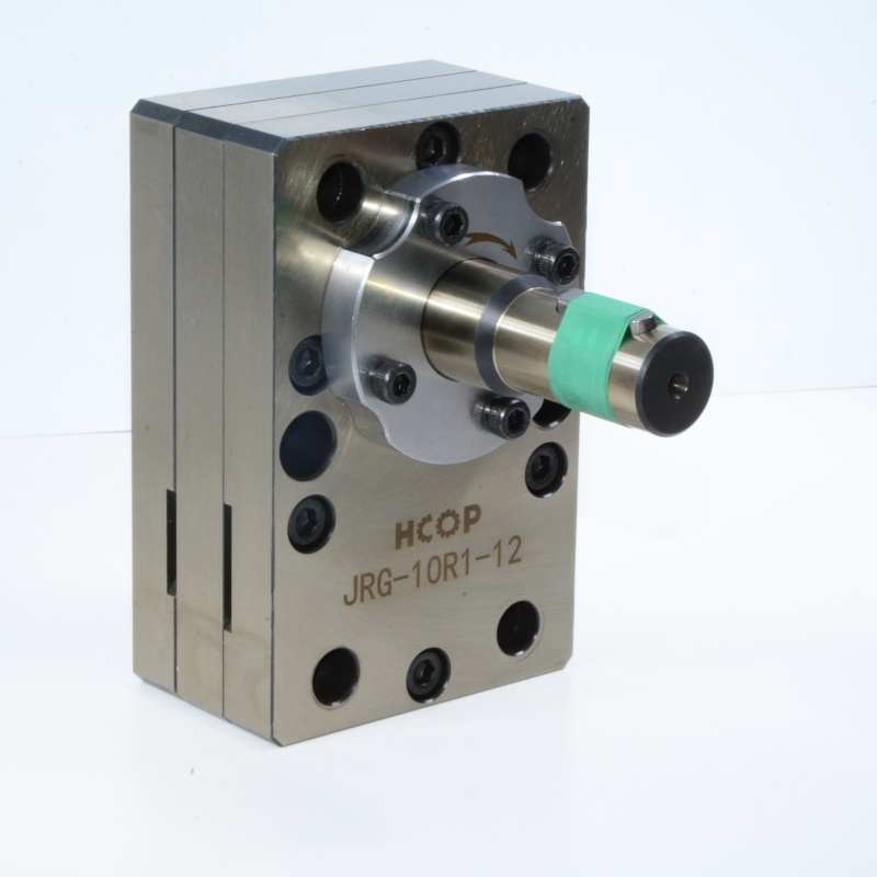


Gear pump, as a compact and reliable volumetric pump, is one of the most widely used equipment in the field of fluid transportation. The core principle is to mechanically cause periodic changes in the working volume through the rotational motion of gears, thereby achieving the suction and discharge of fluids. The specific work process can be decomposed into the following key steps:
1. Basic structure: a pair of meshing gears and a sealed cavity
The core structure of a gear pump usually includes a pair of gears with identical parameters and meshing with each other (one driving wheel and one driven wheel), which are precisely installed inside a tightly fitting pump casing. The gaps between the gear teeth and the inner wall of the pump casing, as well as between the gear end face and the pump side cover plate, are very small, together forming a closed "pump chamber". This cavity is naturally divided into two disconnected working areas by the meshing gears.
2. Inhalation process: Create a local vacuum and extract fluid
When the electric motor drives the driving gear to rotate, the driven gear synchronously rotates in the opposite direction. On the side where the gear disengages, as the teeth gradually exit the meshing space, the volume they occupy is released, causing the sealing chamber volume in that area to increase from small to large, and the internal pressure to decrease, forming a local vacuum (negative pressure state). At this time, the fluid outside the pump is pressurized into this low-pressure chamber under the action of atmospheric pressure (or pressure) at the liquid level of the storage tank, and as the gear rotates, the fluid is filled into the valley space formed by the gear teeth, pump casing, and side cover. This process is the "suction process" of the pump.
3. Transport process: Fluid is trapped between two teeth and carried
The inhaled fluid does not directly pass through the meshing area of the gear, but is enclosed in the enclosed space of the gear valley, like being trapped in moving "small containers". As the gears continue to rotate, these fluid filled valleys will be smoothly carried along the inner wall of the pump casing from the suction side to the discharge side. During this process, the fluid is propelled forward by the gear itself, achieving transport from the inlet to the outlet.
4. Discharge process: The gears mesh again, squeezing and discharging the fluid
When the gear rotates to the discharge side and begins to mesh, the situation is completely opposite to the suction side. The teeth of one gear gradually embed into the valley of another gear, causing the volume of the sealing chamber on that side to decrease from large to small. The decrease in volume leads to severe compression of the fluid and a rapid increase in pressure. High pressure fluid has nowhere to go and can only be forcibly pushed out through the outlet pipeline connected to the discharge chamber, flowing into the subsequent system pipeline. This process is the "discharge process" of the pump.
In summary, the work of a gear pump is a cyclical "volume change" cycle: on the suction side, the disengagement of the gear increases the volume, forming suction; In the middle, the fluid is enclosed and carried; On the discharge side, the meshing of gears reduces the volume and generates pressure. This mandatory and quantitative conveying characteristic makes it particularly suitable for conveying scenarios such as oil and high viscosity fluids that require stable flow rates and certain output pressures. The advantages of its simple structure, durability, and reliability also stem from its direct and efficient working principle.